Type 02 · Framing & rough-in
The floor plan, measured against the plans
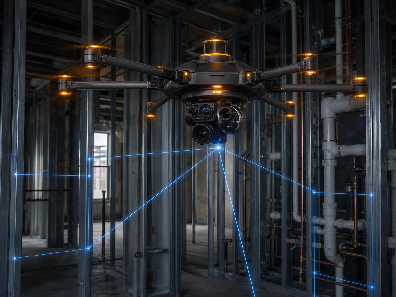
The concrete is up. The drone now flies the plate in blue: every room dimension, every stud, every rough opening, and every pipe — size, material, fitting and slope — checked against the drawing set before drywall hides all of it.
The scan list
Eight checks between framing and close-in
Floor plate dimensions
Overall envelope, bay-to-bay and diagonal squareness against the plan
Room dimensions
Every finished room measured face-of-stud to face-of-stud
Wall location
Partition centerline offset from the gridline and from the core
Stud spacing
16 in or 24 in o.c. verified stud by stud, plus plumb and crown
Rough openings
Door and window opening width, height and header elevation
Plumbing location
Stub-out, flange and drain positions dimensioned from two walls
Pipe size & material
Diameter and material class read per run and matched to the riser diagram
Fittings & slope
Sweep radius, wye vs tee, cleanout access and fall per foot
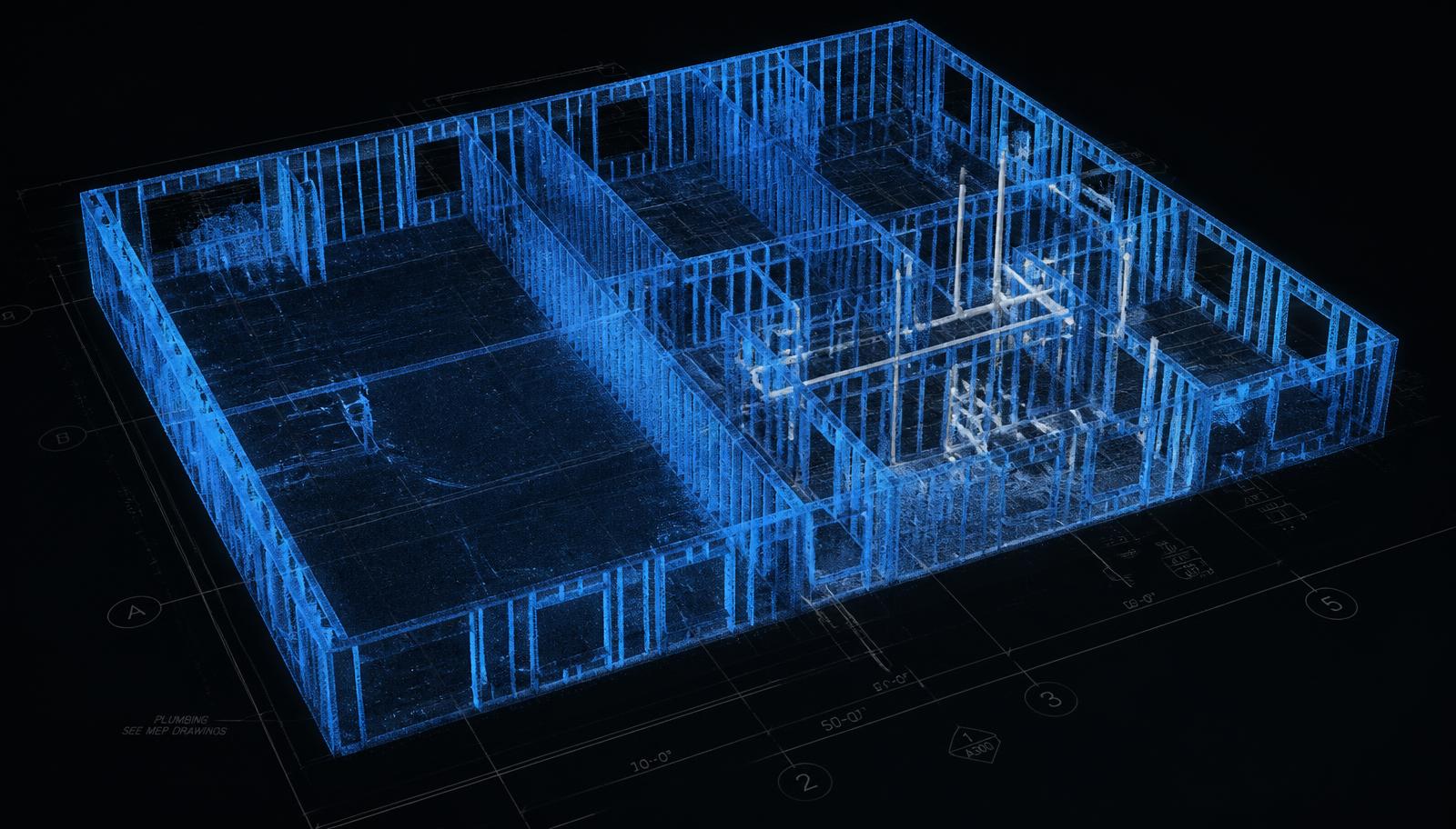
Floor plate · as-built vs plan
Every room dimensioned, then laid over the architectural plan
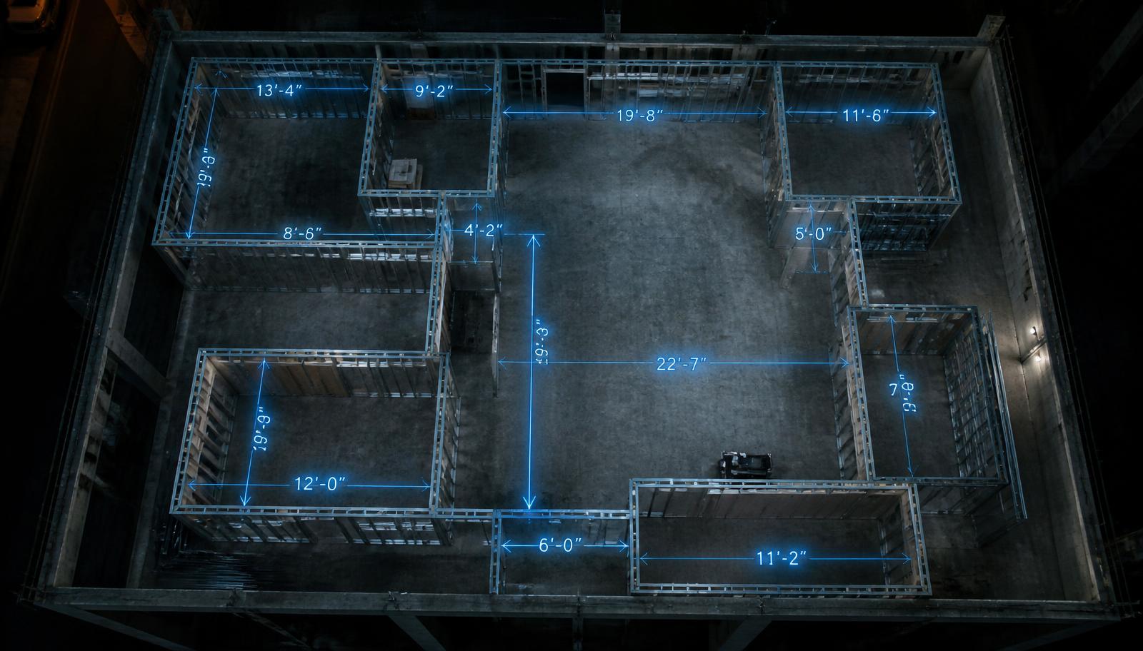
The scan produces a dimensioned as-built plan of the whole floor and registers it to the architectural background. Rooms that drifted, corridors that lost their clear width, and walls that landed on the wrong side of the gridline show up as a colored deviation before the first sheet of board goes up.
- Room dimension tolerance± 1/2 in face-of-stud
- Corridor clear width≥ plan clear, egress width never reduced
- Wall location± 1/4 in from layout line
- Diagonal squareness≤ 1/4 in difference per 20 ft room
- RegistrationControl points shot on the slab, floor to floor
Studs
Stud by stud, not sampled by tape
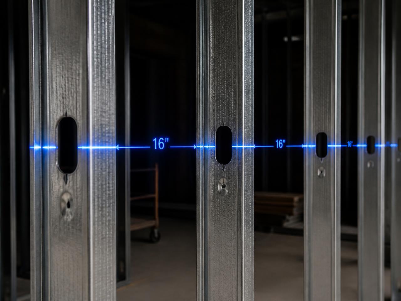
The drone counts every stud in a wall run and reports the pitch as a distribution, so a single stretched bay — the one that leaves a board joint unsupported or a fixture with no backing — cannot hide behind a passing average. Plumb and web crown are read from the same pass.
- Typical spacing16 in o.c. · 24 in o.c. where scheduled
- Spacing tolerance± 1/4 in, board joints must land on a stud
- Stud plumb≤ 1/8 in over the wall height
- Wall straightness≤ 1/4 in in 10 ft
- Top & bottom trackContinuous fastening at spec pitch, deflection gap held
- BackingPresent at every fixture, grab bar and cabinet mark
Rough openings
Openings sized before the doors arrive
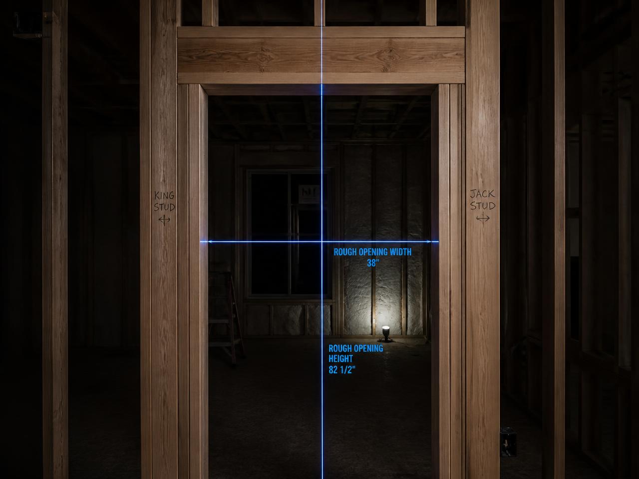
Each opening is measured for width, height, squareness and header elevation, then matched to the door and window schedule. A 1/2 in short opening is a cheap fix at framing and an expensive one after the frames are delivered.
- Door rough openingLeaf width + 2 in, height + 2 1/2 in typical
- Opening tolerance± 1/4 in width and height
- Header elevationConsistent across the floor, ± 1/4 in
- SquarenessDiagonals within 1/8 in
- Schedule matchEvery opening tagged to its door / window mark
Plumbing · location & size
Is the pipe in the right place, and is it the right pipe?
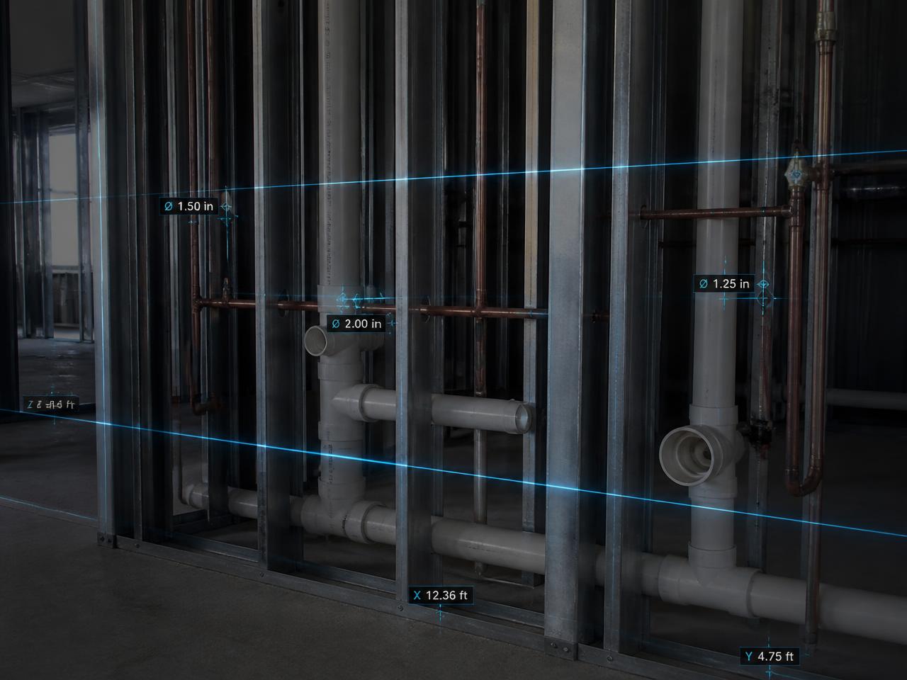
Every run is measured for outside diameter and classified by material — PVC, cast iron, copper, PEX or CPVC — then dimensioned from two fixed references so the fixture lands where the plan says. Nominal size is reported against the riser diagram, so a 1 1/2 in branch on a 2 in line is caught while the wall is still open.
- Lavatory waste1 1/2 in
- Shower / tub waste2 in
- Water closet waste3 in minimum
- VentSized per fixture units, ≥ 1/2 the drain served
- Supply branch1/2 in fixture, 3/4 in group
- Location tolerance± 1/2 in from the plan dimension
Whole-system trace
The drone lights up the entire plumbing system on the wall, not one pipe
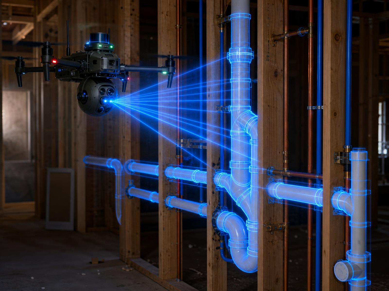
The sensor ball walks the wall end to end and reconstructs the whole network as one connected model — stack, branches, vents, supplies, every fitting and every hanger. The blue laser highlights the complete run as it goes, and each segment is matched against the plumbing drawing: diameter, material, fitting type, direction of flow, fall and connection point. A single wall comes back as one continuous verified assembly rather than a handful of spot dimensions.
Every segment
Each pipe run on the wall is captured as its own element with length, diameter, material and slope
Every fitting
Wyes, sanitary tees, sweeps, couplings, cleanouts and reducers identified by type and orientation
Every connection
Branch-to-stack, vent tie-in and supply take-off checked against the riser diagram
Every support
Hanger and strap pitch measured along the run so an unsupported span is caught before close-in
Wall-level result
- Segments traced41 of 41 on this wall
- Fittings identified18, all matched to the drawing
- Diameter deviations1 — 1 1/2 in branch where 2 in is called
- Slope out of range1 — 0.06 in per ft on the lav branch
- Unsupported span1 — 6 ft 2 in between straps on PVC
- Reported toSuperintendent, PM and plumbing foreman
How the wall is flown
- 01Lateral pass along the wall at stub-out height to pick up branch geometry
- 02Second pass at ceiling height for vents, stack tie-ins and supply drops
- 03Fitting-by-fitting close orbit where the network changes direction
- 04Network assembled, compared to the plumbing sheet, exceptions written
Fittings, curves & fall
The right curve, not just the right pipe
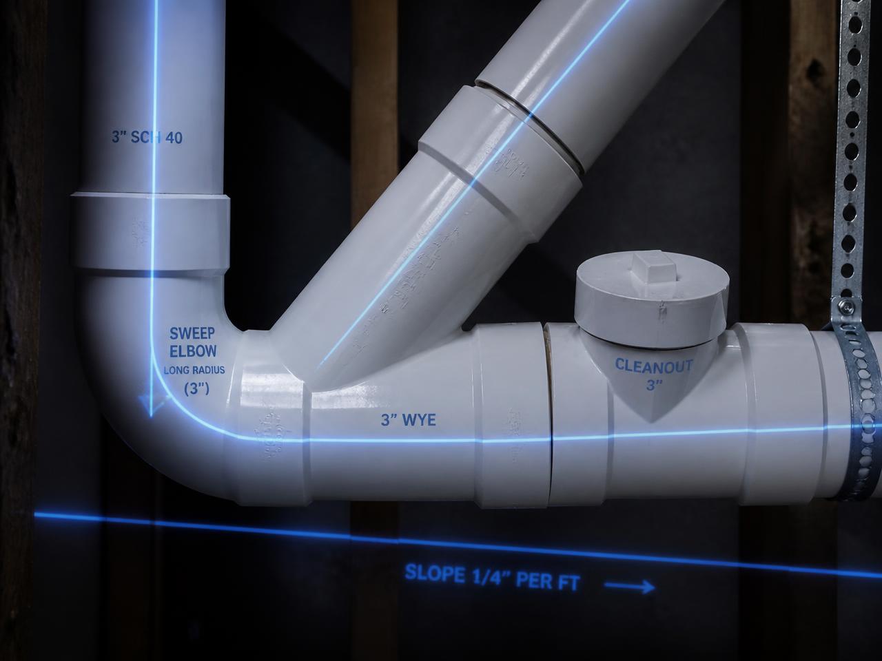
Drainage fails on geometry. The scan measures the radius of every change of direction, identifies the fitting type, and computes the fall along the run from the point cloud — so a short-radius elbow on a horizontal drain or a flat section that lost its slope is flagged as a defect, not discovered as a backup.
- Drain slope, ≤ 2 1/2 in pipe1/4 in per ft
- Drain slope, 3 in and larger1/8 in per ft minimum
- Horizontal direction changeLong-sweep 1/4 bend or two 1/8 bends
- Horizontal to verticalWye and 1/8 bend, no sanitary tee on its back
- CleanoutsEvery 100 ft and at each aggregate 135° of bend
- Support pitchPVC 4 ft horizontal · copper 6–10 ft by size
Fitting verification
Every fitting checked one at a time
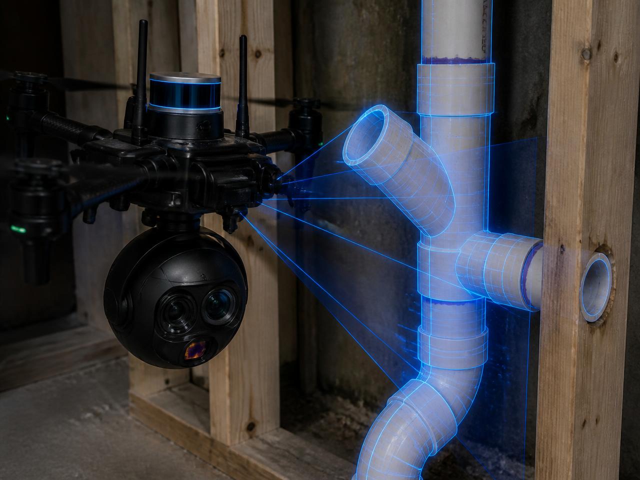
The drone holds a close orbit at each joint and verifies the fitting itself — type, diameter both sides, socket depth, angle, orientation and whether it is legal in that position. A tee used where a wye belongs, a reducer on the wrong side of a branch, or a joint that never got fully seated is caught here, while the wall is still open.
Type & position
Wye, sanitary tee, combo, long sweep, coupling, reducer, cleanout — matched to what the drawing calls for at that joint
Diameter each side
Run and branch measured independently so a 2 in branch off a 3 in run is confirmed, not assumed
Socket depth
Pipe fully seated in the hub; a short insertion shows as a bright band of exposed pipe
Angle & orientation
45° vs 90°, sweep direction with the flow, tee never laid on its back on a horizontal-to-vertical turn
Solvent weld / joint
Continuous primer and cement witness ring around the hub, no dry joint, no gap at the shoulder
Transitions
Dielectric or approved coupling where materials change; no reducing bushing where a fitting is required
Cleanout access
Plug reachable and clear of the finished wall line, with the required swing clearance
Support at the joint
A hanger within the required distance of every fitting so the joint carries no bending load
| Tag | Fitting on drawing | Measured by drone | Result |
|---|---|---|---|
| F-01 | 3 in combo wye + 1/8 bend | 3 x 3 x 2 combo, sweep with flow | Pass |
| F-02 | 2 in long-sweep 1/4 bend | 2 in long sweep, seated 1 1/2 in | Pass |
| F-03 | 3 in sanitary tee, vertical | Sanitary tee laid horizontal, on its back | Reject |
| F-04 | 2 x 1 1/2 in reducer at branch | Reducing bushing in the hub | Reject |
| F-05 | 3 in cleanout at 135° aggregate | Cleanout present, plug 1/2 in behind wall line | Rework |
| F-06 | 1/2 in copper 90° elbow | 1/2 in elbow, joint fully soldered | Pass |
The fitting list goes to the superintendent, the project manager and the plumbing foreman only — a punch list for the crew, not a filing for anyone outside the job.
Fixture set-out
Flanges and stub-outs dimensioned from two walls
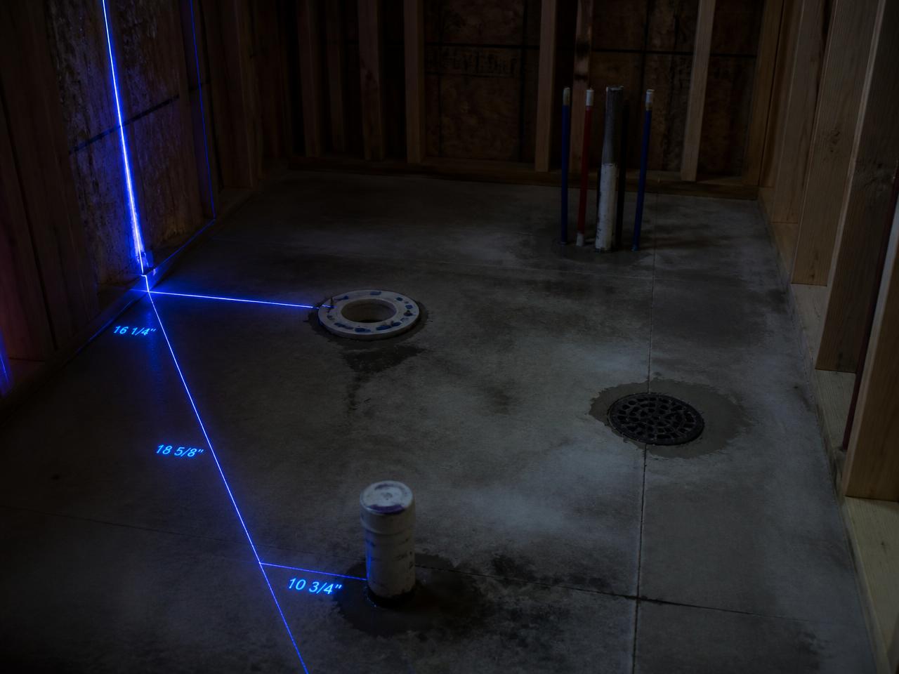
A closet flange an inch off centre is a tile layout problem, a clearance violation and a change order. The scan locates every penetration in the slab and the wall from two perpendicular references and reports the fixture clearances to your management team so they are corrected in-house, before anyone outside the job ever looks at them.
- Water closet centerlineMin 15 in to any wall or fixture
- Water closet clearance21 in clear in front (24 in typical spec)
- Lavatory centerlineMin 15 in to side wall, 30 in between bowls
- Rough-in offset12 in from finished wall, standard
- Penetration tolerance± 1/4 in on flange and drain centres
- Sleeve & firestopEvery rated penetration logged with its location
Deliverable
A pre-close-in release the trades can sign against
As-built plan overlay
Dimensioned floor plan registered to the architectural background, with every deviation over tolerance located to the room.
Rough-in record
Pipe runs classified by size, material, fitting type and slope, reconciled line by line against the plumbing drawings.
In-wall archive
Point cloud and imagery of every wall captured before board, so a later fixture, anchor or leak has a record to work from.
Values shown are typical US practice under the IPC/UPC and standard framing tolerances. The approved drawings, project specification and governing code edition always control.
Sonar · ultrasonic ranging
Laser and LiDAR are the primary measurement layer, but they lose confidence on dark, wet, dusty or mirror-like surfaces and at very short standoff. Sonar fills that gap: ultrasonic pulses resolve the small stuff — millimetre-scale gaps, offsets, thin clearances and shallow voids — in low light, through airborne dust and against surfaces a laser skips off. On this page it is what confirms stud face flatness, tight pipe-to-framing clearances and fitting standoff in dim, dusty rough-in space.
What you’ll receive
Framing & plumbing rough-in — point cloud (LAS/E57) registered against the coordination model + PDF deviation report before the wall closes.
Open formats only: GeoTIFF · LAS/LAZ · E57 · OBJ/FBX · DWG/DXF · LandXML · PDF · CSV. No proprietary viewer required.
What it costs when nobody's watching
Rough-in errors are a fitting swap today and a wall demo next month.
up to 70%
of rework traces to engineering, design and coordination errors — the class MEP rough-in errors fall into.
Source: General industry claim, repeated across rework literature — no single primary citation
up to 9.5%
of total project cost lost to design-related rework on industrial projects.
Source: Burati et al., peer-reviewed quality-deviation study
$2.5M–$5M
RFI and change-order tax on a representative $50M commercial build.
Source: Flikt.AI 2026 benchmark drawing on Dodge and FMI/Autodesk — vendor synthesis, illustrative
48% · 26%
of rework attributed to poor collaboration, and to trade miscommunication specifically.
Source: PlanGrid / FMI, Construction Disconnected (2018)
5–9%
of total project cost lost to rework typically; 20–30% on troubled projects.
Source: CII; Dodge Data & Analytics, SmartMarket Report on Project Rework (2018)
~$31B / yr
rework tied to bad, missing or wrong field data.
Source: PlanGrid / FMI, Construction Disconnected (2018)
Government-grade sources (BLS, OSHA, NIST/NIBS) are cited as published. Industry research (Arcadis, FMI/Autodesk, CII, NSC) is survey- and estimate-based. Vendor case studies and vendor pricing pages are labeled where used and should be read as documented examples, not industry averages.