Type 07 · CMU walls
Everything in a block wall disappears the moment grout goes in
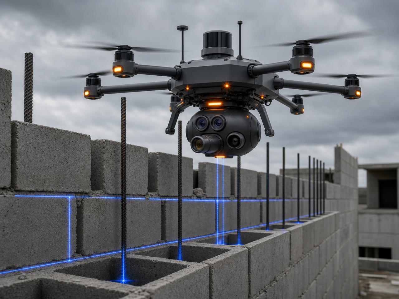
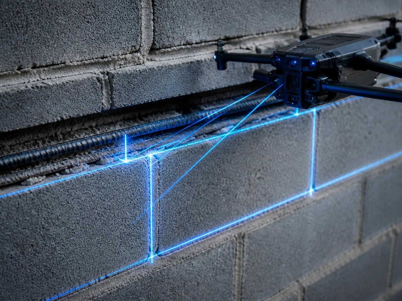
CMU Pre-Grout Verification: the drone scans the wall in the hour before the pump truck arrives. Vertical bar cells, bar size, spacing, laps, anchorage, bond beams, opening sizes and wall plumb — all measured in blue laser and compared line by line to the structural drawings, while a fix still costs a mason an hour instead of a saw and a core rig.
The system
Plans → scan → discrepancy engine → report
Plans / BIM
The structural drawings and the reinforcement schedule load as the reference model.
Scan
A multi-sensor flight walks the wall: LiDAR geometry, high-res RGB into every open cell.
Computer vision
Bars detected and sized, cells indexed, joints and openings measured off the point cloud.
Discrepancy engine
Every measured value differenced against spec; only the exceptions reach a human.
Pre-grout · the money window
Inside every open cell, before it is filled
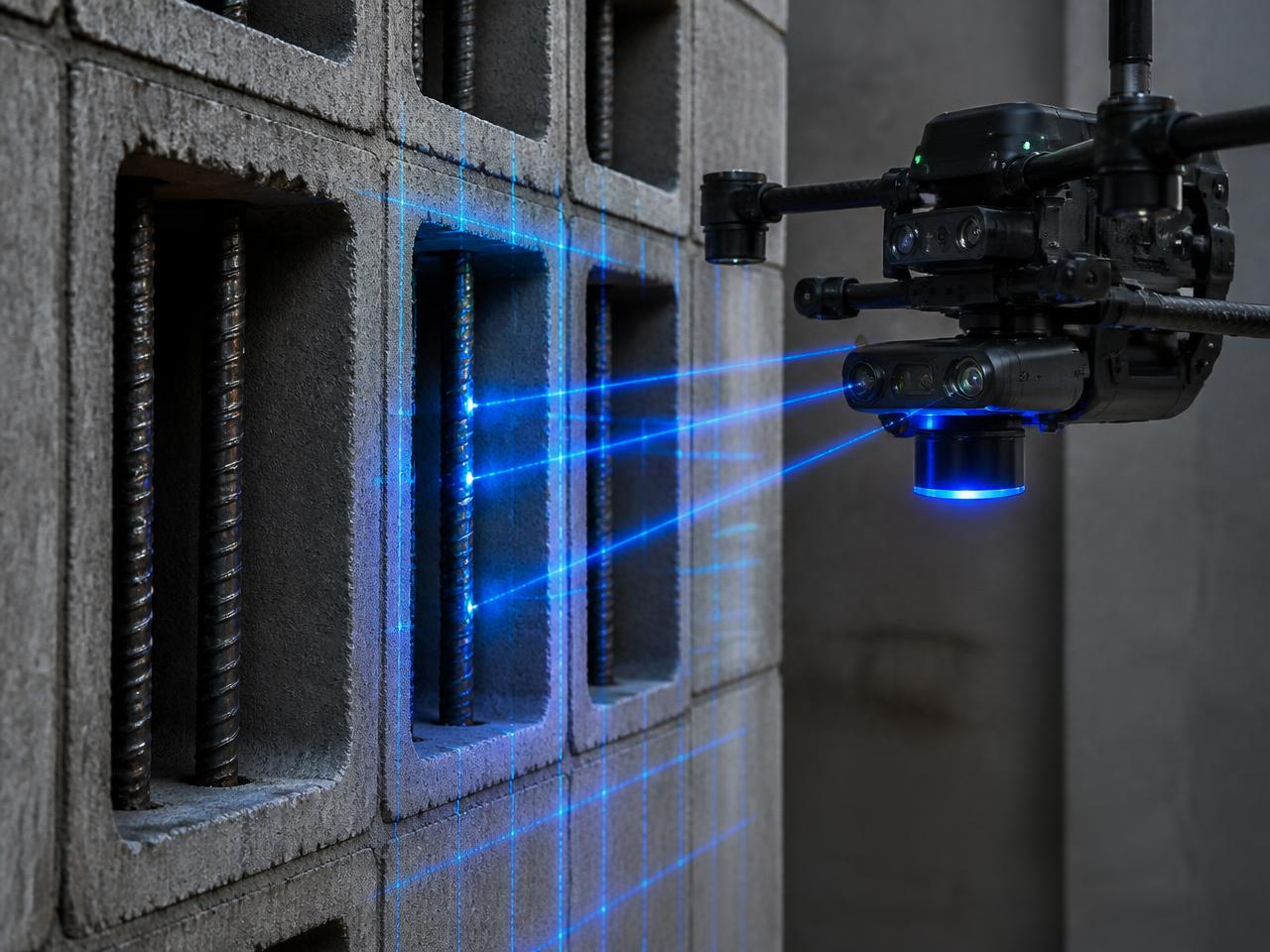
The drone flies the top of the wall and the open face, reading down into each cell. It identifies which cells carry steel, sizes the bar off the deformation pattern and diameter, measures the centre-to-centre spacing along the run, and reads lap length wherever two bars overlap. Dowel projection out of the slab and hook anchorage into the bond beam are captured in the same pass.
- Bar size#4 / #5 / #6 classified
- SpacingMeasured O.C. along the wall
- Lap spliceAgainst the schedule, per bar
- AnchorageDowel projection and hook
- Cell indexReinforced cells vs schedule
Cost of not catching it
A missed bar found before grout is a mason dropping steel into an open cell. The same miss found after grout is coring, epoxy dowels, an engineer's repair detail and a hold on everything stacked behind that wall — routinely a five-figure item on one wall, and it lands in the rework column that costs US construction roughly $65B a year.
Geometry · location, plumb, straightness
The wall is either on the gridline or it is not
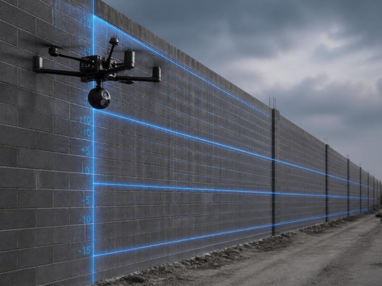
A single laser plumb plane is projected down the wall and the LiDAR return is differenced against it, giving lean at every course and a bow map along the full run. Wall location is tied to site control, so an offset from the gridline shows as a number, not an argument. Top-of-wall elevation is picked up in the same sweep.
- Wall locationOffset from gridline, in ⅛"
- PlumbLean per lift and per course
- StraightnessBow map along the run
- Top of wallElevation vs control
- Thickness8" / 12" verified
Openings · lintels · embeds
Every opening measured before the frame shows up
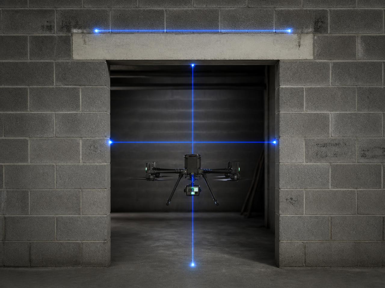
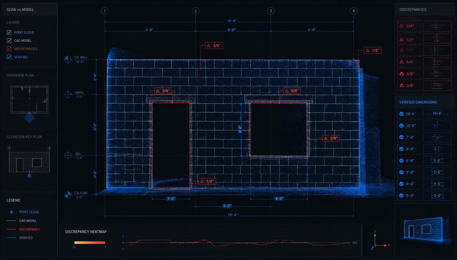
Rough opening width, height and position are measured off the point cloud and matched to the door and window schedule. Over each opening the lintel is checked for size, bearing length each side and reinforcement before it is covered. Plates, anchor bolts, sleeves and MEP block-outs are located in the same model and compared to the drawings.
- Rough openingsWidth, height, position
- Head / sillElevation vs schedule
- LintelsSize, bearing, reinforcement
- EmbedsPlates, bolts, anchors, sleeves
- PenetrationsLocation and size vs BIM
Workmanship · joints and bond beams
Joint by joint, course by course
A close-in pass reads bed and head joint thickness, full bedding and tooling quality across the elevation, flags chipped or cracked units, and confirms control joints land where the drawings put them. At the bond beam course the horizontal steel is counted, sized and its lap measured before the channel is filled.
- Bed joints⅜" ± ⅛" checked per course
- Head jointsFull, no voids
- Control jointsLocation vs plan
- Bond beamBar count, size, lap
- Unit conditionCracks, chips, displacement
Stage map
Slab → first course → rebar → pre-grout → post-grout → roof tie-in
Slab & first course
Top-of-slab elevation, wall layout lines, dowel position out of the slab, first course bedded true
Erection
Wall location on gridline, length, height, thickness, coursing and top-of-wall elevation
Rebar, pre-grout
Vertical bar in the correct cells, bar size, spacing, lap length, anchorage into slab and bond beam
Bond beams & lintels
Beam course location, bar count and configuration, lintel size, bearing and reinforcement over openings
Embeds & penetrations
Plates, bolts, anchors, sleeves and MEP penetrations checked against the drawings before grout
Post-grout
Grouted cells confirmed against the required-cell schedule; crack, chip and displacement survey
Coverage
What gets checked, and what sensor gets it
| Inspection | What gets checked | How it is captured |
|---|---|---|
| Wall location / layout | Wall built on the correct gridline offset | LiDAR + survey control |
| Wall dimensions | Length, height, thickness, opening sizes | LiDAR + photogrammetry |
| Plumbness | Wall leaning out of vertical over its height | LiDAR plumb plane |
| Straightness | Bowing and waviness along the wall run | LiDAR deviation map |
| Elevation | Top-of-wall and opening head/sill elevations | LiDAR tied to site control |
| Door / window openings | Width, height and position of every opening | LiDAR + photogrammetry |
| Rebar placement | Vertical and horizontal steel in the specified cells | RGB before grout |
| Rebar size & spacing | Correct bar at the correct interval, on centre | High-res imaging + computer vision |
| Rebar laps | Splice length at every bar joint | Imaging + measurement |
| Embedment / anchorage | Dowel projection and hook into slab and beam | Visual + measurement, pre-grout |
| Bond beams | Beam course reinforcement and configuration | Imaging before grout |
| Grout cells | Every required reinforced cell actually filled | Visual during pour; NDT after |
| Grout consolidation | Voids and honeycombing inside the cell | Specialist NDT — not a camera job |
| Mortar joints | Joint thickness, full bedding, workmanship | High-resolution RGB |
| Control joints | Correct location and construction | RGB + plan comparison |
| Lintels | Size, location, bearing and reinforcement | RGB + LiDAR |
| Embedded items | Plates, bolts, anchors and sleeves | RGB + LiDAR |
| MEP penetrations | Location and size of every sleeve or block-out | LiDAR + BIM comparison |
| Cracks & damage | Cracks, chipped units, displaced block | High-resolution RGB |
| Surface defects | Damaged CMU and poor workmanship | RGB + computer vision |
| As-built vs drawings | Whether the wall matches the structural plans | LiDAR + BIM/CAD comparison |
Grout consolidation is the honest exception: voids inside a filled cell need specialist NDT, not a camera. We document what is verifiable and say plainly what is not.
The report
One line per discrepancy, located by wall and grid
| Location | Item | Specified | Observed | Status |
|---|---|---|---|---|
| Wall A-12 | Vertical rebar spacing | 32" O.C. | 40" O.C. at Grid C4 | Hold grout |
| Opening 104 | Rough opening width | 6'-0" | 5'-10¾" (1¼" short) | Hold grout |
| Wall B-7 | Wall location off gridline | Gridline + 8'-4" | Gridline + 8'-6⅛" (2⅛" out) | Hold grout |
| Wall A-12 | Lap splice length | 48 dₘ (30") | 22" at cell 14 | Hold grout |
| Wall C-3 | Plumb over 12'-0" lift | ≤ ½" | ⅜" out | Review |
| Wall C-3 | Bed joint thickness | ⅜" ± ⅛" | 9/16" at course 6 | Review |
| Wall D-1 | Bond beam bar count | 2 – #5 continuous | 2 – #5 continuous | Verified |
Tolerances shown are common defaults. The structural drawings, the specification and the engineer of record override every figure here.
Deliverable
A dated as-built of the wall as it stood the hour before grout
Pre-grout clearance
A wall-by-wall go / hold in management's hands before the pump truck is called, with photo evidence into every cell.
Discrepancy list
Specified vs observed for each flag, located by wall mark and gridline, with the measured delta in eighths.
As-built record
Point cloud overlaid on the structural model and archived, so the wall that got covered can still be shown years later in a dispute.
Scope note: some structural masonry inspections must legally be performed or certified by a building official, special inspector or engineer. We supply the measurement and documentation layer to management — we do not replace that sign-off.
Sonar · ultrasonic ranging
Laser and LiDAR are the primary measurement layer, but they lose confidence on dark, wet, dusty or mirror-like surfaces and at very short standoff. Sonar fills that gap: ultrasonic pulses resolve the small stuff — millimetre-scale gaps, offsets, thin clearances and shallow voids — in low light, through airborne dust and against surfaces a laser skips off. On this page it is what confirms cell alignment and grout-void depth inside the block, plus mortar joint thickness at close standoff.
What you’ll receive
CMU pre-grout verification — marked-up DXF overlay on the wall elevations + PDF exception report + point cloud (LAS/E57) of the wall before grout.
Open formats only: GeoTIFF · LAS/LAZ · E57 · OBJ/FBX · DWG/DXF · LandXML · PDF · CSV. No proprietary viewer required.
What it costs when nobody's watching
Grout is the deadline. After it, every finding is demolition.
~$65B / yr
U.S. construction rework cost — about 5% of $1.3T in total construction spend.
Source: Autodesk / FMI, Harnessing the Data Advantage in Construction (2020/2022)
5–9%
of total project cost lost to rework typically; 20–30% on troubled projects.
Source: CII; Dodge Data & Analytics, SmartMarket Report on Project Rework (2018)
52%
of total cost overrun on a project traces back to rework.
Source: CII, analysis of 150+ industrial construction projects
up to 70%
of rework traces to engineering, design and coordination errors — missed cells, wrong spacing, shifted openings.
Source: General industry claim, repeated across rework literature — no single primary citation
48%
of rework attributed to poor communication and missing information.
Source: PlanGrid / FMI, Construction Disconnected (2018)
$60.1M · 12.5 months
average U.S. construction dispute value and duration.
Source: Arcadis, 2025 Global Construction Disputes Report
Government-grade sources (BLS, OSHA, NIST/NIBS) are cited as published. Industry research (Arcadis, FMI/Autodesk, CII, NSC) is survey- and estimate-based. Vendor case studies and vendor pricing pages are labeled where used and should be read as documented examples, not industry averages.